Fundamental Laws that govern electric circuits:
○Ohm's Law
○Kirchhoff's Laws
○Ohm's Law
○Kirchhoff's Laws
OHM'S LAW
Ohm's law states that the voltage v across a resistor is directly proportional to the current i flowing through the resistor.
That is
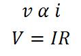
which is the mathematical form of Ohm’s law. R is constant of proportionality and has the ability to resist the flow of electric current which is measured in the unit of ohms, designated Ω.
Linear resistor is a resistor that obeys Ohm’s law that has a constant resistance.
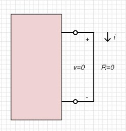
Short circuit (R=0)
Similarly an element with R is equals to infinity is known as an open circuit- is a circuit element with resistance approaching infinity.
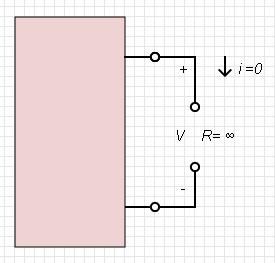
Open circuit (R= ∞)
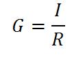
Conductance (G) – Siemens (S)
Conductance is the ability of an element to conduct electric current that is measured in mhos or Siemens. Conductance also is the reciprocal of resistance R.
Example:
Determine voltage (v), conductance (G) and power (p) form the figure below.
I = 10kΩ
Determine voltage (v), conductance (G) and power (p) form the figure below.
I = 10kΩ
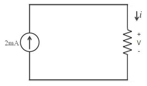
Solution:
Using the formula of Ohm's Law, V=IR
V=IR
V = 2mA (10kΩ)
V = 20V
Using the formula of Ohm's Law, V=IR
V=IR
V = 2mA (10kΩ)
V = 20V
Node, Branches and Loops
Elements of an electric circuit can be interconnected in several ways we need to understand the basic concepts of network topology.
Branch- represents a single element (i.e. voltage, resistor)
Node - is the meeting point between two or more branches
Loop – any closed path in the circuit.
Elements of an electric circuit can be interconnected in several ways we need to understand the basic concepts of network topology.
Branch- represents a single element (i.e. voltage, resistor)
Node - is the meeting point between two or more branches
Loop – any closed path in the circuit.
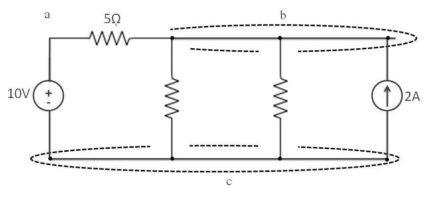
In the picture above, identify how many branches, nodes and modes the given picture have.
KIRCHHOFF'S LAW
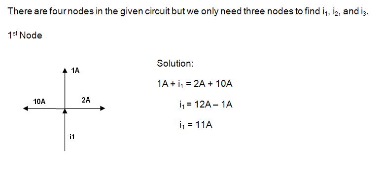
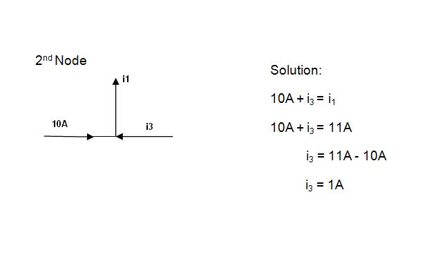
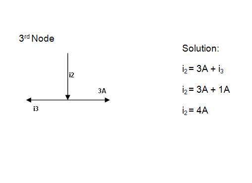
Kirchhoff's Current Law (KCL)
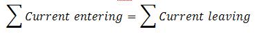
Kirchhoff's Current Law defined as the algebraic sum of current entering or leaving a node (or closed boundary) is zero.
Current enters = +ve
Current leaves = -ve
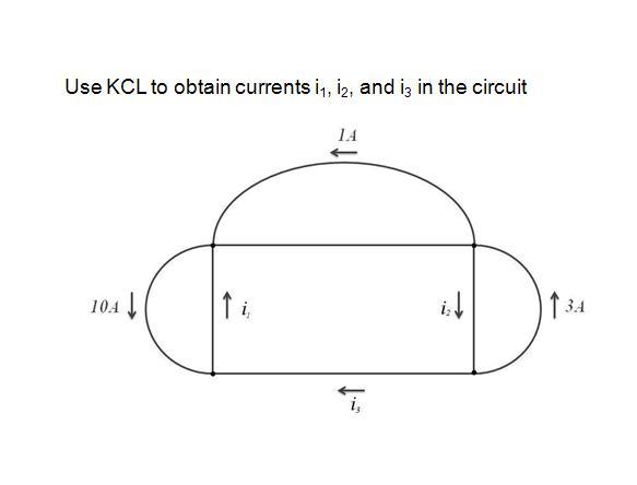
Example:
Kirchhoff's Voltage Law (KVL)
Kirchhoff's Voltage Law is defined as the algebraic sum of voltage (rises and drops in a loop is zero.)
KVL can be applied in two ways:
•By taking either a clockwise or counter-clockwise trip around the loop.
• Either way, the algebraic sums of voltages around the loop is zero.
Sum of voltage drops = Sum of voltage rises.

To illustrate KVL in this circuit, the sign on each voltage is the polarity of the terminal encountered first as we travel around the loop. We can start with any branch and go around the loop either clockwise or counterclockwise. Supposed we start with the voltage source (Vs) and go clockwise around the loop.
+Vs - V1 - V2 - V3 =0 (equation 1)
or you can also do the counterclockwise loop
-Vs + V1 +V2 + V3 =0 (equation 2)
Both equations can be use to solve for the voltages in the circuit.
+Vs - V1 - V2 - V3 =0 (equation 1)
or you can also do the counterclockwise loop
-Vs + V1 +V2 + V3 =0 (equation 2)
Both equations can be use to solve for the voltages in the circuit.
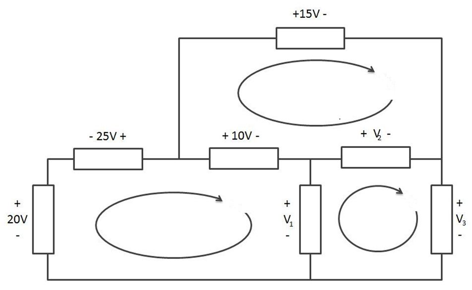
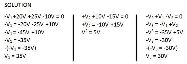
Example:
Use KVL to obtain V1, V2 and V3
 RSS Feed
